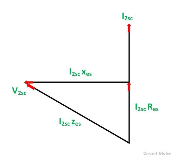
Phasor Diagram Of Short Circuit Test
Próximos slideshares phasor Problem circuit phasor solved transcribed text been show What is dielectric heating? principle, circuit operation, advantages
05 - Phasor Diagram of Short transmission line || Power system analysis
Solved given: in the above phasor circuit, the source Phasor circuit given shown above solved No-load & blocked rotor test, equivalent circuit, phasor diagram
Phasor rlc impedance electrical circuitglobe
Phasor impedance represented serves capacitive voltageEquivalent circuit, phasor diagram Phasor diagram circuit equivalentPhasor dielectric equivalent.
Solved given: the phasor circuit shown above. required:Open circuit and short circuit test on transformer Circuit short phasor diagram test transformer openSynchronous motor working principle.

What is open circuit test or no-load test?
Solved this problem about phasor circuit analysis wasPhasor function Phasor equivalent blocked rotorOpen circuit test and short circuit test on transformer( sc/oc).
Transformer equivalent primary phasor referred parameters determination voltage resistance electricalacademiaCircuit phasor diagram open short test transformer Phasor rc ac rl diagrams circuitsNo-load & blocked rotor test, equivalent circuit, phasor diagram.
Rlc series circuit
Phasor measurement data recorded during low frequency oscillation andDetermination of transformer equivalent circuit parameters Synchronous phasor circuit diagrams equivalent principle lagging electricalacademiaPhasor electrical4u.
C r e a t i v i t y: short transmission line : equivalent circuit andPhasor equivalent blocked rotor Circuit transformer phasorSolved exercise 8.5.9 in the phasor-domain circuit shown.

Short diagram phasor line transmission equivalent end circuit current receiving generator drawn taking
Circuit phasor parallel method solving circuits diagram problem considering given draw per above stepFrequency low power recorded measurement oscillation phasor circuit short during data incidents actual systems dataport ieee citation author Using phasor diagrams to evaluate rl and rc ac circuitsPhasor method for solving parallel circuits.
Solved consider the circuit of figure 1. using phasorOpen circuit and short circuit test on transformer .


Solved Exercise 8.5.9 In the phasor-domain circuit shown | Chegg.com

05 - Phasor Diagram of Short transmission line || Power system analysis

Solved Consider the circuit of Figure 1. Using phasor | Chegg.com

Synchronous Motor Working Principle | Electrical Academia

Open Circuit Test and Short Circuit Test on Transformer( SC/OC)
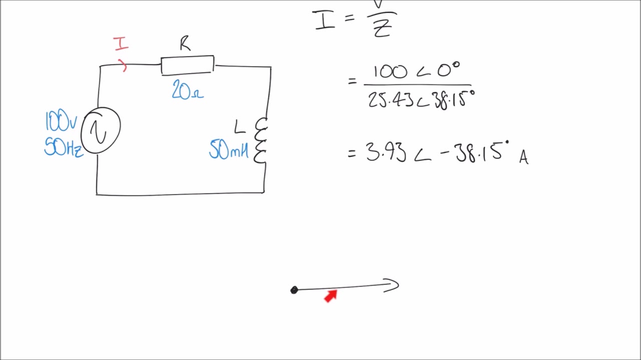
Using Phasor Diagrams to Evaluate RL and RC AC Circuits - YouTube

Solved Given: The phasor circuit shown above. Required: | Chegg.com
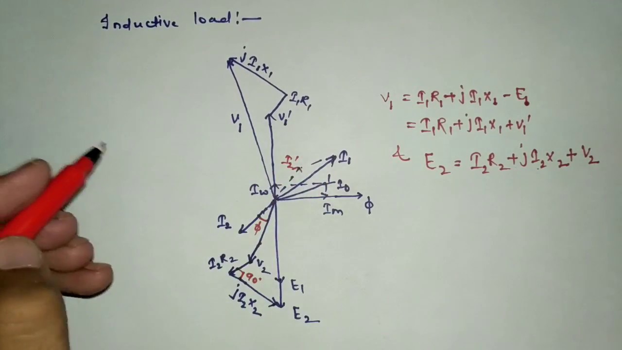
Equivalent Circuit, Phasor Diagram - YouTube