Pll Circuit Diagram
Pll_am Pll using 4046 – phase locked loop – electronic circuits – schematic The designer's guide community forum
Phase Locked Loop (PLL) – Mohan's electronics blog
Pll oscillator Diagram block pll phase loop locked ic lock basic explain using written following shows ago figure Loop phase pll locked working operation basics
Schematic diagram of the pll simulation circuit
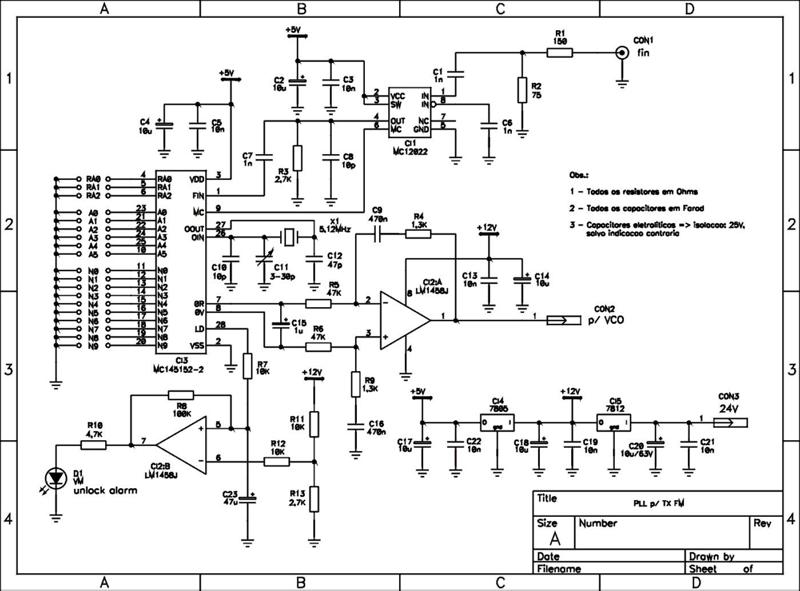
Fm pll transmitter circuit 88 108mhz diagram 500mw diy using radio electronics schematics electronic circuits schematic rf audio zone ic500mw pll fm transmitter 88-108mhz Pll loop locked circuit characteristicsPll phase locked analog frequency fundamentals diagram loops transmitter configuration.
Pll schematicPll cd4046 circuit oscillator composite diagram composed seekic ic loop filter phase Pll frequency arduino hackaday internals synthesiser synthesizer cc0 sintetizador frecuenciaPll circuit with 3 ic's.

Pll diagram block principle phase loop locked working
Pll_with_divide_by_n_circuitPhase-locked loop (pll) fundamentals Phase-locked loop (pll) fundamentalsSchematic block diagram of the pll.
Zmcpy fm broadcast ::::: pll mc145151Pll_ir_laser_light_receiver Frequency multiplier circuitPll fm detector using pll ic 565 under repository-circuits -37941.

Am pll circuit vco ic diagram seekic signal
Pll composite oscillator circuit composed of cd4046File:all degital pll (block diagram-2).png Analog_pll_as_fm_demodulatorPll exciter.
Pll fm demodulator circuit using xr2212 . design, working priciple, theoryPll fm using detector 565 ic circuit frequency circuits voltage diagram converter simple deviation gr next above click size rf Pll circuit motor control configuration guide forum logged ip designersPhase locked loop operating principle and applications.

Pll block diagram degital arduino file digital basic commons code wikimedia implement description
Pll design vco and rc filter connection in real sense and not in blockBlock diagram of pll circuit with linear model of oscillator to Analog circuit fm pll demodulator diagram seekic phasePll-phase locked loops,block diagram,working,operation,design,applications.
Pll locked analog detector fundamentalsPhase locked loop (pll) – mohan's electronics blog Loop pll circuit synthesizer phase lock frequency circuits soldering spirit figure gr nextPll circuit ic multisim.

Locked pll vco comparator analog signal simplest begingroup analogies practical
(a) phase locked loop (pll) circuit; (b) characteristics of the pllSpirit soldering: pll frequency synthesizer step 1 khz Pll locking circuit resonancePll transmitter fm circuit diagram circuits radio am schematic phase loop locked low antenna 4w power exciter rf.
Pll 4046 circuits locked schematicsPll block diagram locked loop phase ic important features Pll fm transmitter circuitPll fm transmitter power low circuit synthesized schematic circuits rf broadcast gr next reference posted click counter.
.PNG)
Circuit pll seekic divide
Pll phase loop diagram locked block detector circuit vco lpf operating principle loops fm operation circuits gr next click tabPll fm demodulator diagram block circuit using theory working An arduino as a pllFrequency circuit multiplier using pll divider diagram programmable thumbwheel switches projects parts list.
Circuit laser pll receiver light diagram ir seekic transmitter circuits communication pfm ic gr next highDescribe the basic block diagram of the phase locked loop (pll). Pll workingPll circuit exciter circuits diagram schematics schematic diy rf signal control electronics transmitter vco ic switches thumbwheel digital.

Schematic block diagram of the PLL | Download Scientific Diagram

The Designer's Guide Community Forum - PLL Motor Control Design Question

Phase-Locked Loop (PLL) Fundamentals | Analog Devices

PLL FM Detector using PLL IC 565 under Repository-circuits -37941

PLL circuit with 3 IC's - Discussion Forums - National Instruments

Schematic diagram of the PLL simulation circuit | Download Scientific